What is scan-to-CAD?
Scan-to-CAD is the process of turning a physical object into an editable engineering model. The scan is only the first step of four.
1. Capture
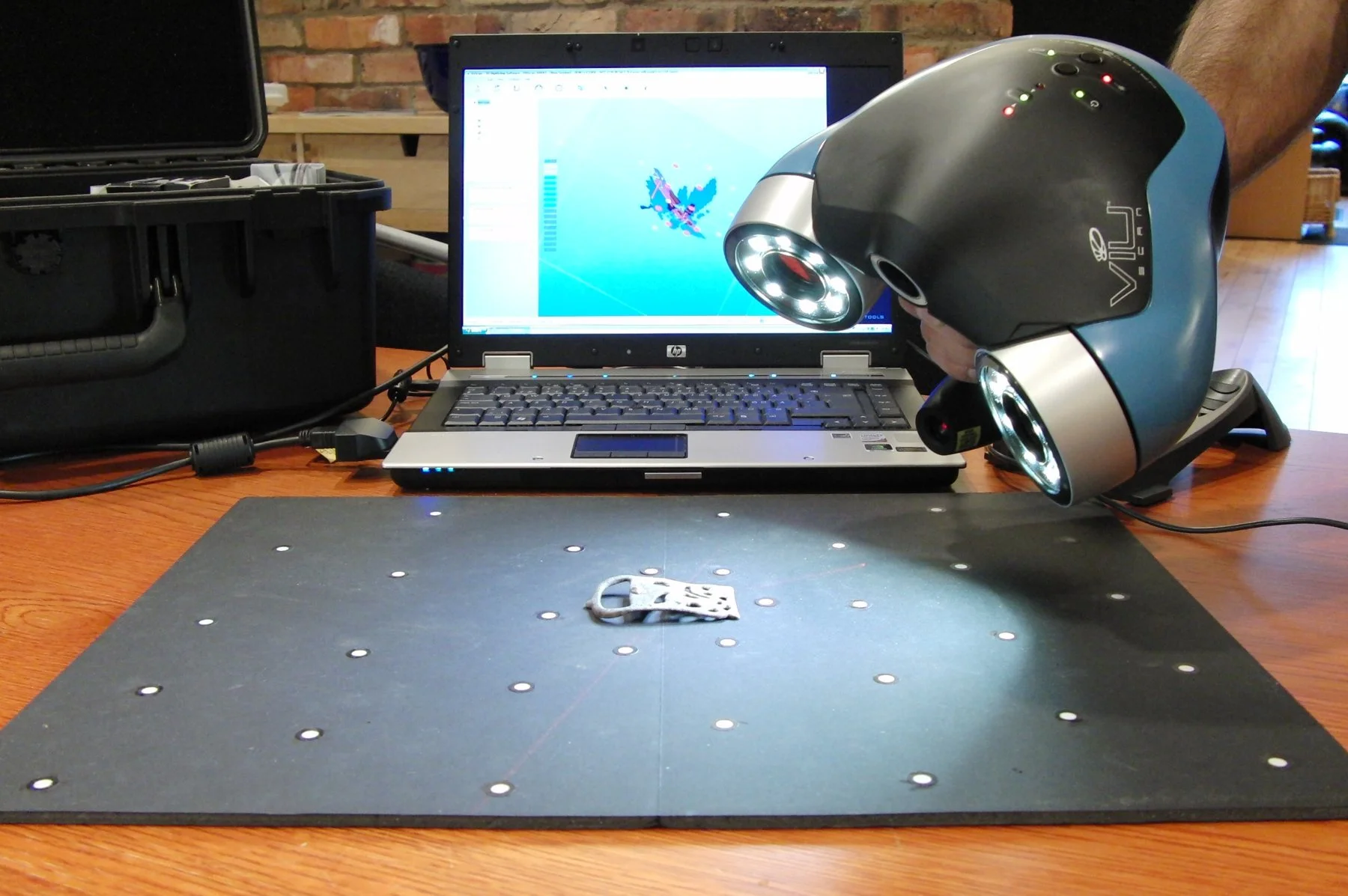
3D scanning records the surface of a real object as a dense set of measured points — a point cloud. Multiple scan positions are aligned so the whole geometry is covered, including features that are hidden from any single viewpoint.
2. Mesh
The point cloud is processed into a mesh: a continuous triangulated surface. A mesh is useful for inspection, visualisation and some manufacturing routes, but it is a record of shape, not a description of design intent. You cannot change a hole diameter in a mesh.
3. Model
The engineering work happens here. The mesh is interpreted into parametric CAD geometry: planes, cylinders, fillets, features and dimensions with intent behind them. This step requires judgement — deciding which deviations in the scan are the designed geometry, which are wear, and which are manufacturing tolerance.
This is why reverse engineering is not automatic. A worn shaft should usually be modelled as its nominal design, not as its worn condition.
4. Verify and document
The finished model is compared back against the scan data to confirm deviation is within tolerance, and drawings are produced so the part can actually be made or procured.
When it is worth doing?
Typical cases: an obsolete component with no supplier and no drawings; a part modified on site years ago with no record; equipment that must be replicated or adapted; a legacy asset that needs documenting before it fails. In each case the alternative is measuring by hand and hoping, which does not scale to complex geometry.
What you should receive?
A defensible deliverable set includes the registered scan data, the parametric CAD model in a usable format, a deviation report against the scan, and manufacturing drawings. A single mesh file is not a reverse-engineering deliverable.
